Background
Absorption of γ radiation occur by three different effects: The photoelectric effect, the Compton effect and pair formation (for more, visit the NucWik page about Gamma-ray Interactions). A NaI crystal will emit light when γ radiation is absorbed. If we optically couple the crystal to a sensitive light-detector (a photo multiplier tube), we can measure the amount of light emitted and therefore also the γ radiation. In this way we can construct a γ detector and we call it a NaI-scintillator detector (to scintillate means emits light).The amount of light is proportional to the amount of energy deposited in the detector. The light detector is so fast that it's able to measure the light from each individually absorbed γ ray. By analysing the pulse height from the detector (which is proportional to the amount of light) we can make a picture of the distribution of energy deposited in the detector. I.e. we make a histogram where each column represent the number of events within a small energy range - we will get a plot of event intensity as a function of energy deposited in the detector. Such a histogram we call a spectrum.
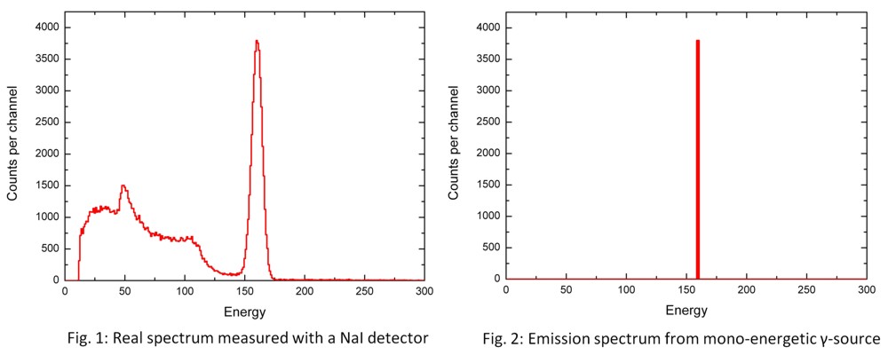
If we have a source which only emits γ rays with a single energy, its spectrum should look like Fig. 1. However, if we measure such a source with a NaI scintillation detector, the spectrum we get look like Fig. 2. The reason is of course the manner γ rays are absorbed in the detector. A large fraction of the γ's will be absorbed by the Compton effect and this severely distorts the spectrum. If the energy is high enough we will also get pair formation that further distort the spectrum.

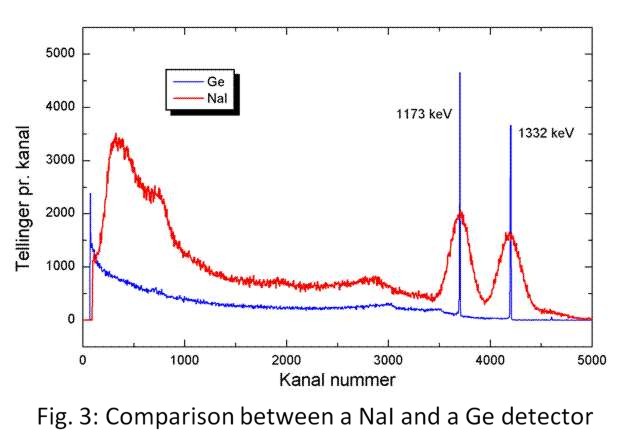
Other types of γ detectors work not by light emission (scintillation), but are based on semi-conductor technology. Here the γ-sensitive element is actually part of an electronic circuit and acts like an electrical diode. Radiation hitting the diode will generate a current pulse which is amplified and measured by the electronic circuit. Such detectors are usually named Ge-detectors since the Ge-detector crystal which constitute the larges part of the diode is made of this element. Ge-detectors have much better energy resolution than NaI detectors, but are much more expensive.

For any kind of detecter, the measurement of the generated signal (wheater it is an electric signal or a light pulse) will never be 100% accurate. The error in the measurement will widen the peaks and generally smooth the spectrum. Thus, details will be more difficult to distinguish. The detector error is generally discussed in therms of the detectors response function. A Ge-detector has a better response function than a NaI detector. The simulation program presented here will enable you to change the response function to see how it affects the measured spectrum. This is also something which generally can not be done with a real detector.
Software
A program written in LabView can be downloaded. In order to run the program you must have the associated plug-in installed in your computer, the plug-in can be downloaded from National Instrument (you must register to do so, but it is free of charge). Once the plug-in is installed, you can run the simulation program.Here are the relevant links:
- LabView Simulation Program (written by Jon Petter Omtvedt at UiO)
- Simulation program installer (includes National Instrument plug-in)
- Source code (not needed unless you want to change the program and/or add your own features). Please share any improvements you make with the NucWik community!
Exercises
Exercise 1: Detection of γ radiation
In a real detector one can not turn the different absorption effects on and off - they will always be on. However, in this exercise we will use the simulation program and then you have full control of which effects should be active or not. You can even vary the intensity of the different effects.The program or "virtual instrument" enables you to control four detector properties: The response function (responsible for the measurement error) and the absorption coefficients for the photo electrical effect, the Compton effect and pair formation. Furhtermore the application let you chose if your source should emit γ rays with one, two or three different energies. And you can vary the intensity of which each energy is emitted with.
Perform the following experiments with the program, where you instruct it to use only a single γ energy with 662 keV of energy (that will correspond the the γ emission from a 137Cs source):
- Make a "perfect" spectrum, as it would be measured if only the photo electrical effect was present and no detector error. I.e. set the application's response function to 0, the photo electrical effect to 100%, the Compton effect to 0% and par formation to 0%.
- Make a spectrum which has no detector error (response function = 0), but only absorbs γ rays with the Compton effect (photo electrical effect = 0%, Compton effect = 100% and pair formation = 0%). Compare this spectrum to the one you made in the previous step. Which one is most suitable for analysing the radiation energy and intensity from a γ source?
- Make a spectrum where only the photo electrical effect is at play, but select a response function of 100. Can you explain the shape of the response function? Tip: Some times the primary electron (the one which the γ ray transferred its energy to) will not excite the detector crystal as much as it should have done. This might be due to impurities in the crystal or that the electron exits the crystal before it has been stopped completely. In other words we will have some events which can have anything from 0% and up to 100% of the correct energy. For example, an electron which deposit 50% of its energy and then escapes the crystal will be registered as a count with only half of the "correct" energy.
- Make a spectrum with the response function set to 100, the photo electrical effect equal to 50% and the Compton effect equal to 50%. Compare this to a spectrum from a real NaI detector, as shown in Fig. 1 above.
For each experiment you should write down the parameters you have used and store the spectrum as an image file. In this way you can incorporate your spectra in your report (if your teachers demand you write one). You store the spectra by right clicking it and then choosing the menu command "Export Simplified Image". It's the same procedure as when you pick pictures from web-pages in most browsers.
Exercise 2: Analysing spectra with multiple γ lines
Use the simulation program you used in exercise 1, but this time you select three different γ ray energies: 400 keV (10% intensity), 450 keV (50%) and 800 keV (100%).- Make a spectrum with an ideal detector (response function = 0, photo electrical effect = 100%, Compton effect = 0% and pair formation = 0%).
- Compare this spectrum with what you get if the response function is 10 and 100.
- What happens if you turn on the Compton effect?
Conclusion
In your report's conclusion, you should try to explain what you have learned about γ spectroscopy. E.g. how does the detectors energy resolution (the response function) influence the quality/uncertainty of the spectrum? And what would be the advantage of selecting a detector made in such a way that the photo electrical effect is as dominant as possible?Development History and Contact Person
This exercise was originally conceived by Jon Petter Omtvedt (UiO) and used in radiochemistry courses at UiO. It was adapted for NucWik as part of the CINCH project.If you have comments, suggestions, similar programs (in any language) or anything else relevant, please write in the discussion box below (but you must be a registered user) or send your feed-back to NucWik-post@kjemi.uio.no.